Remote Control Car
with Raspberry Picos
25 November 2024

Description
The Goal: To create a remote controllable car that can move in 4 directions and its remote with 2 Raspberry Picos.
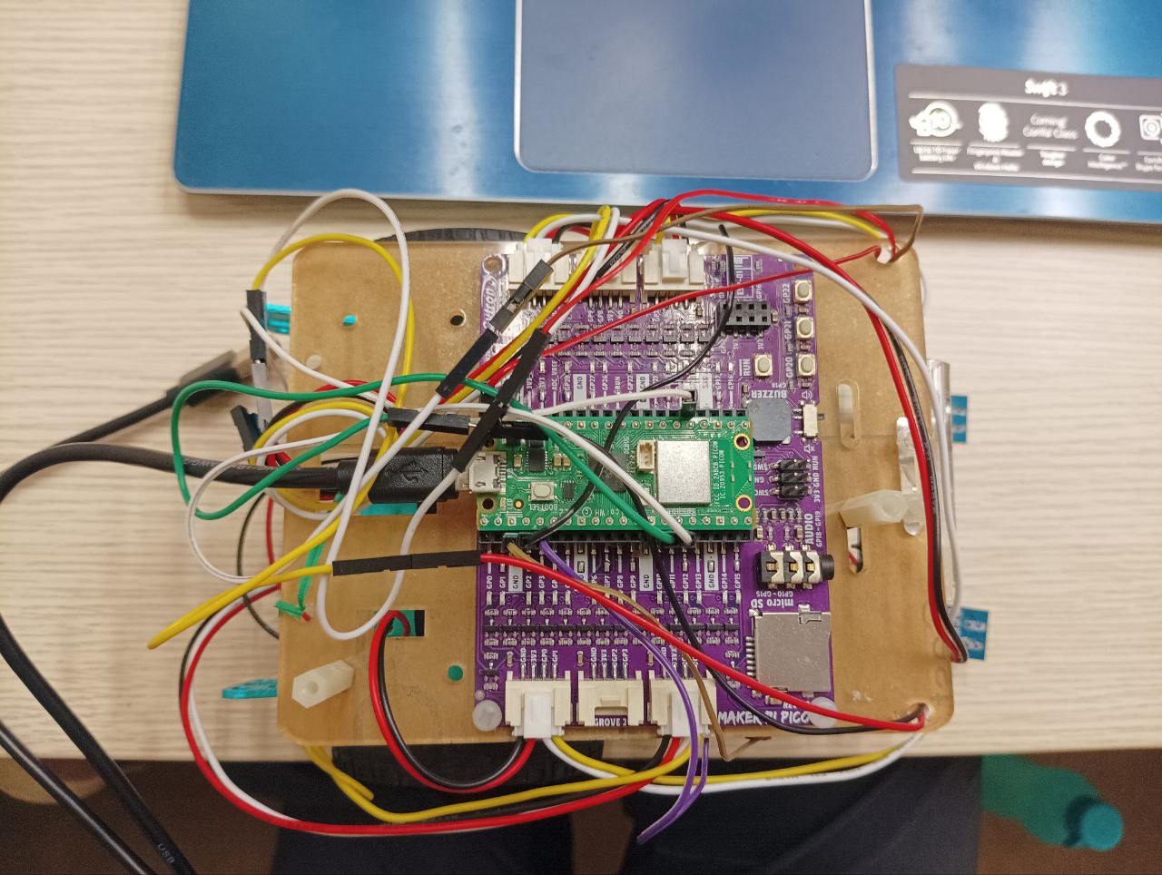
Responsibilities: Embedded Systems Developer & Tester
Key Contributions
- Architected a Finite State Machine (FSM)
- Developed Wheel Encoder Component
- Developed Motor with Fine-tuned Proportional-Integral-Derivative (PID)
- Developed Ultrasound Sensor Feature
Tech Stack
- Language: C
- Tools & Packages: CMake, FreeRTOS, Arduino, TCP
Key Features & Functionality
1) Remotely Controlled: The car can be controlled with a controller remotely made with another Raspberry Pico via TCP.
2) Line Reading: A Line Reading mode was developed to allow the remote control car to follow a printed line on the ground based on light sensor values.
3) Distance Tracking: A Wheel Encoder component tracks the distance travelled by the car.
4) Motor with PID: The motor will adjust its own duty cycle value based on the desired duty cycle using the PID algorithm.
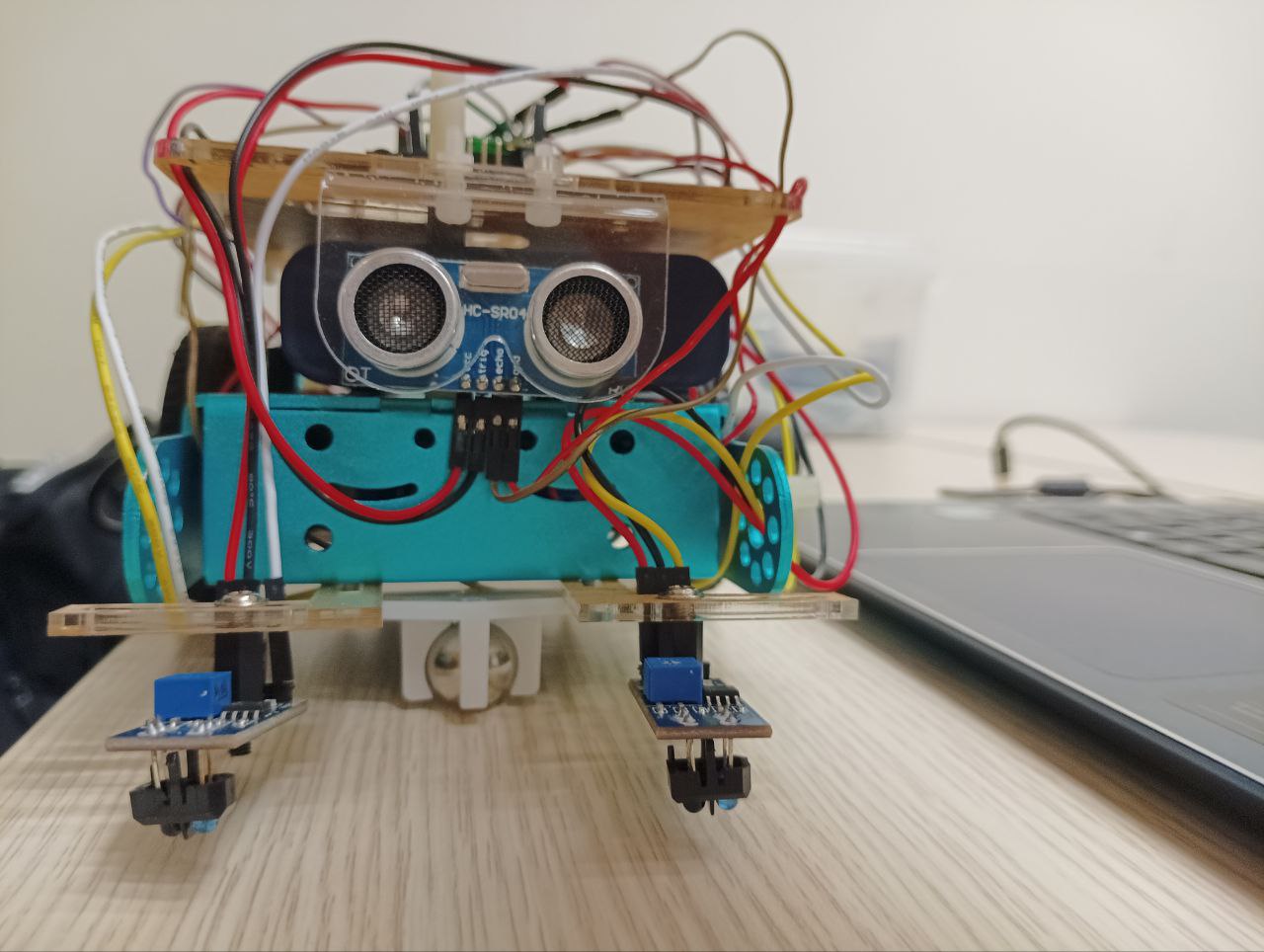
5) Ultrasonic Sensor: An Ultrasonic Sensor component tracks the distance the car is from whenever it encounters an obstacle.
6) Dashboard: Tracks the car’s current status and tracked metrics (like distance travelled, ultrasonic sensor detection, etc).
Technical Challenges & Solutions
Technical Challenges & Solutions - Motor Stability
Technical Challenges & Solutions - Motor Stability - Issue
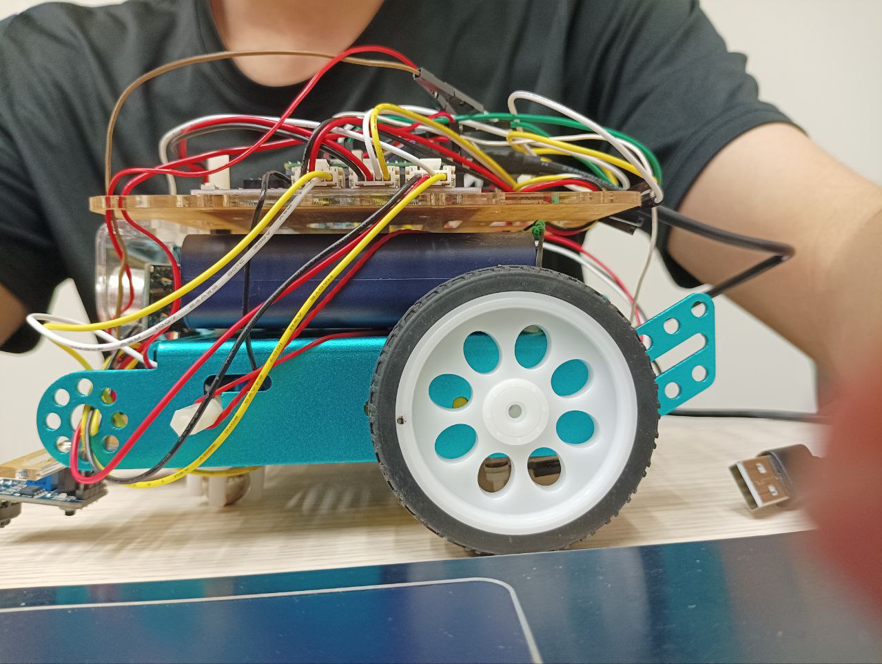
The first issue was the car’s motor. Having two motors, each with its own motor speed, is difficult to balance as having a different motor speed on one wheel from the other could cause the car to drift in a direction. Hence, a flexible solution was needed to overcome this issue so that it could work with any set of motors that the car was constructed with.
By searching online for solutions, a popular industrial solution was the PID - Proportional-Integral-Derivative.
To simplify this, the PID is essentially an algorithm that utilises and modifies these 3 variables in a system:
1) Desired value (that can be defined by the user)
2) Current value (that was retrieved by a sensor)
3) Correction value (that is calculated based on Error to be added to the current value in the next cycle)
By constantly retrieving the current value and using it to calculate the error between the desired value, a correction value could be calculated. Finally, by setting the current value of variable as the correction value, a self-adjusting feedback system can be created thus achieving balance in the two motors.
However, what variables can we use for the PID algorithm in order to achieve balance in the two motors?
In this remote control car project, there are these following information that are being tracked/known:
1) Pulse Per Revolution (number of electrical signals an encoder sends for every one full 360 degrees rotation of its shaft.)
2) Wheel Circumference (A fixed number that describes the circumference of the wheel used in the car construction)
3) Duty Cycle that controls how fast the motor turns
As such we can use these variables for the following:
- Feedback (Input): By counting how many pulses occur over a set time interval (e.g., every 50ms), you can calculate the current velocity.
- Output: The Duty Cycle. This is what the PID “adjusts” to reach the target speed.
Technical Challenges & Solutions - Motor Stability - The Logic Flow
The PID algorithm runs in a fast, repeating loop. Here is how the variables can be used:
Calculate Current Speed: Current_Speed = (Pulses_Counted / Pulses_Per_Rev) * (Circumference / Time_Interval)

Calculate Error: Error = Desired_Speed - Current_Speed

Compute PID Terms:
    P: Kp * Error (Immediate reaction)
    I: Ki * Sum_of_Errors (Fixes long-term drift)
    D: Kd * Rate_of_Change (Prevents overshooting)

Update Duty Cycle: New_Duty_Cycle = P + I + D
Technical Challenges & Solutions - Motor Stability - Fine-Tuning in Reality
Once the software logic has been implemented into the motor component, it is time for us to fine tune the PID Terms mentioned in the previous section.
When the fine-tuning process was taking place, it can be seen that the controller car is jittering quite a bit when trying to adjust its PID. As such there were a few things that was needed to be fine tuned:
1) Lower the Deravative Gain (Kd)
2) Lower the proportional gain (Kp)
3) Check the time interval of when the PID algorithm is called
Technical Challenges & Solutions - Motor Stability - The Lesson
If a lesson was to be learnt from this entire project, it would be that real life physics does not play nicely with code. This came as a shock this was my first time developing an embedded system that moves, reacts and interacts with the real physical world.
For example, as I was fine-tuning the PID values. I realised that tuning on a wooden surface is completely different from tuning on a croncrete ground. Due to each material’s friction, different values were needed to ensure that the car controller was moving at its best performance.
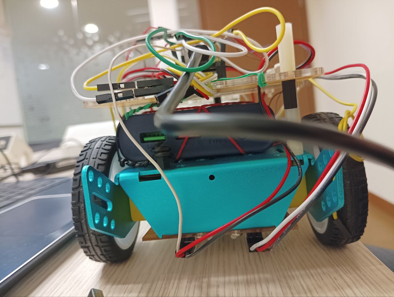
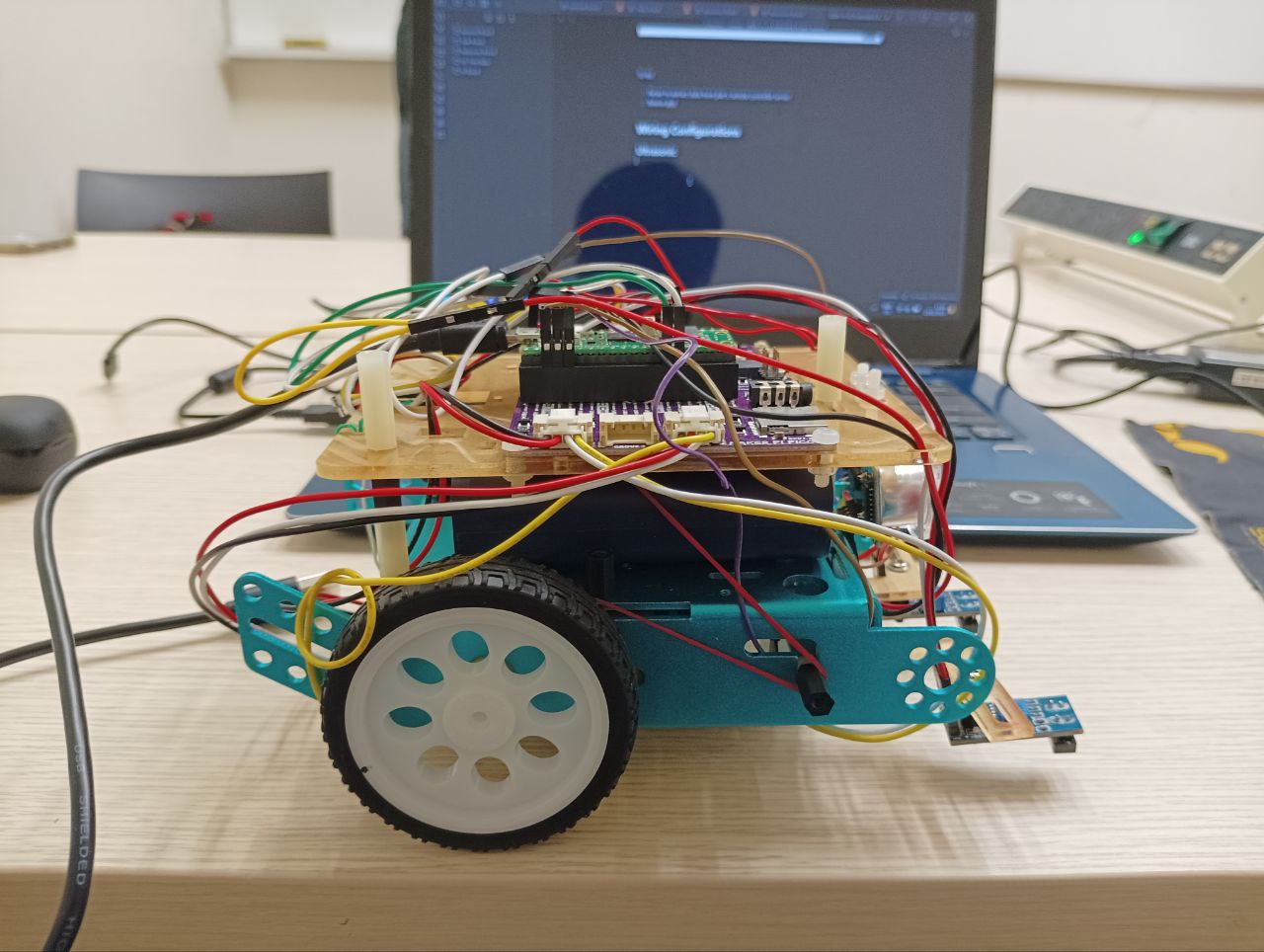
Moreover, debugging a certain issue like why a motor is not moving became twofold. I would need to check both the code and the hardware wiring to see if there were any mistakes like unplugged wires or loose cables made.
All in all, it was a good project to learn from. I realized how difficult working with hardware could be due to the increased effort one must take whenever they test the device.